Category: Link Aggregation
Nexus 1000V LACP offload and the dangers of in-band control
A while ago someone sent me the following comment as part of a lengthy discussion focusing on Nexus 1000V: “My SE tells me that the latest 1000V release has rewritten the LACP code so that it operates entirely within the VEM. VSM will be out of the picture for LACP negotiations. I guess there have been problems.”
If you’re not convinced you should be running LACP between the ESX hosts and the physical switches, read this one (and this one). Ready? Let’s go.
Don’t Try to Fake Multi-chassis Link Aggregation (MLAG)
Martin sent me an interesting challenge: he needs to connect an HP switch in a blade enclosure to a pair of Catalyst 3500G switches. His Catalysts are not stackable and he needs the full bandwidth between the switches, so he decided to fake the multi-chassis link aggregation functionality by configuring static LAG on the HP switch and disabling STP on it (the Catalysts have no idea they’re talking to the same switch):
The Data Center Fabric architectures
Have you noticed how quickly fabric got as meaningless as switching and cloud? Everyone is selling you data center fabric and no two vendors have something remotely similar in mind. You know it’s always more fun to look beyond white papers and marketectures and figure out what’s really going on behind the scenes (warning: you might be as disappointed as Dorothy was). I was able to identify three major architectures (at least two of them claiming to be omnipotent fabrics).
Business as usual
Each networking device (let’s confuse everyone and call them switches) works independently and remains a separate management and configuration entity. This approach has been used for decades in building the global Internet and thus has proven scalability. It also has well-known drawbacks (large number of managed devices) and usually requires thorough design to scale well.
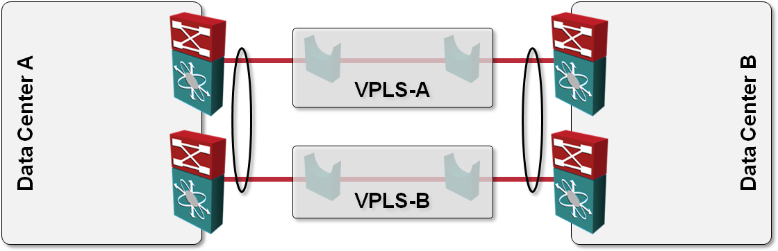
L2 DCI with MLAG over VPLS transport?
One of the answers I got to my “How would you use VPLS transport in L2 DCI” question was also “Can’t you just order two VPLS services, use them as P2P links and bundle the two links into a multi-chassis link aggregation group (MLAG)?” like this:
vSwitch in Multi-chassis Link Aggregation (MLAG) environment
Yesterday I described how the lack of LACP support in VMware’s vSwitch and vDS can limit the load balancing options offered by the upstream switches. The situation gets totally out-of-hand when you connect an ESX server with two uplinks to two (or more) switches that are part of a Multi-chassis Link Aggregation (MLAG) cluster.
Let’s expand the small network described in the previous post a bit, adding a second ESX server and another switch. Both ESX servers are connected to both switches (resulting in a fully redundant design) and the switches have been configured as a MLAG cluster. Link aggregation is not used between the physical switches and ESX servers due to lack of LACP support in ESX.
VMware vSwitch does not support LACP
This is very old news to any seasoned system or network administrator dealing with VMware/vSphere: the vSwitch and vNetwork Distributed Switch (vDS) do not support Link Aggregation Control Protocol (LACP). Multiple uplinks from the same physical server cannot be bundled into a Link Aggregation Group (LAG, also known as port channel) unless you configure static port channel on the adjacent switch’s ports.
When you use the default (per-VM) load balancing mechanism offered by vSwitch, the drawbacks caused by lack of LACP support are usually negligible, so most engineers are not even aware of what’s (not) going on behind the scenes.
Intelligent Redundant Framework (IRF) – Stacking as Usual
When I was listening to the Intelligent Redundant Framework (IRF) presentation from HP during the Tech Field Day 2010 and read the HP/H3C IRF 2.0 whitepaper afterwards, IRF looked like a technology sent straight from Data Center heavens: you could build a single unified fabric with optimal L2 and L3 forwarding that spans the whole data center (I was somewhat skeptical about their multi-DC vision) and behaves like a single managed entity.
No wonder I started drawing the following highly optimistic diagram when creating materials for the Data Center 3.0 webinar, which includes information on Multi-Chassis Link Aggregation (MLAG) technologies from numerous vendors.
MLAG and Load Balancing
FullMesh added an excellent comment to my Multi-Chassis Link Aggregation (MLAG) and hot potato switching post. He wrote:
If there are two core routing switches and two access switches which are MLAGged together in both directions, and hosts that are dual-active LAGged to the pair of access switches, then the traffic would stay on whichever side the host places it.
He also opened another can of worms: load balancing in MLAG environment is dictated by the end hosts. It doesn’t pay to have fancy switches that support L3 or L4 load balancing; a stupid host implementing destination-MAC-address-based load balancing can easily ruin your day.
Multi-Chassis Link Aggregation (MLAG) and Hot Potato Switching
There are two reasons one would bundle parallel Ethernet links into a port channel (official term is Link Aggregation Group):
- Transforming parallel links into a single logical link bypasses Spanning Tree Protocol loop avoidance logic; all links belonging to the port channel can be active at the same time (see also: Multi-Chassis Link Aggregation basics).
- Load sharing across parallel links in a port channel increases the total bandwidth available between adjacent L2 switches or between routers/hosts and switches.
Ethan Banks wrote an excellent explanation of traditional port channel caveats (proving that 1+1 sometimes does not equal 2); things get way worse when you start using Multi-Chassis Link Aggregation due to hot potato switching (the switch tries to forward packets toward destination MAC address as soon as possible) used by all MLAG implementations I’m familiar with.
External Brains Driving an MLAG Cluster
Juniper has introduced an interesting twist to the Stacking on Steroids architecture: the brains of the box (control plane) are outsourced. When you want to build a virtual chassis (Juniper’s marketing term for stack of core switches) out of EX8200 switches, you offload all the control-plane functionality (Spanning Tree Protocol, Link Aggregation Control Protocol, first-hop redundancy protocol, routing protocols) to an external box (XRE200).