Generate Partial Device Configurations with netlab
At ITNOG 10, I’ve seen something that I haven’t seen in a very long time: a mini-Interop-style physical lab using a dozen devices from different vendors. The network core was a leaf-and-spine fabric with off-path BGP route reflectors and numerous other devices attached to it.
I’ve configured a few networks in the past, so I know it must have been a beast to configure all those devices by hand (and fix all the IP addressing errors), but then a thought struck me: unless one wants to practice configuring IP addresses, it might be a good idea to use netlab to generate the IP addressing plan and partial device configurations.
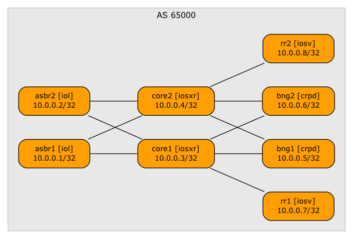
Core network topology
Here’s the process I would use:
- Describe target lab topology in netlab topology file (life will be easier if you name it
topology.yml). - Print the wiring plan with the netlab report wiring command. Tweak the topology file until it’s just right. If needed, change the interface names or indices to match your physical gear1. Here’s the wiring report I got from my topology file:
| Origin Device | Origin Port | Destination Device | Destination Port |
|---|---|---|---|
| asbr1 | Ethernet0/1 | core1 | GigabitEthernet0/0/0/0 |
| asbr1 | Ethernet0/2 | core2 | GigabitEthernet0/0/0/0 |
| asbr2 | Ethernet0/1 | core1 | GigabitEthernet0/0/0/1 |
| asbr2 | Ethernet0/2 | core2 | GigabitEthernet0/0/0/1 |
| core1 | GigabitEthernet0/0/0/2 | bng1 | eth1 |
| core1 | GigabitEthernet0/0/0/3 | bng2 | eth1 |
| core2 | GigabitEthernet0/0/0/2 | bng1 | eth2 |
| core2 | GigabitEthernet0/0/0/3 | bng2 | eth2 |
| core1 | GigabitEthernet0/0/0/4 | rr1 | GigabitEthernet0/1 |
| core2 | GigabitEthernet0/0/0/4 | rr2 | GigabitEthernet0/1 |
- Use the wiring plan to connect lab devices
- Print the addressing plan with the netlab report addressing. Here’s the initial addressing report I got:
| Node/Interface | IPv4 Address | IPv6 Address | Description |
|---|---|---|---|
| asbr1 | 10.0.0.1/32 | Loopback | |
| Ethernet0/1 | 10.1.0.1/30 | asbr1 -> core1 | |
| Ethernet0/2 | 10.1.0.5/30 | asbr1 -> core2 | |
| asbr2 | 10.0.0.2/32 | Loopback | |
| Ethernet0/1 | 10.1.0.9/30 | asbr2 -> core1 | |
| Ethernet0/2 | 10.1.0.13/30 | asbr2 -> core2 | |
| core1 | 10.0.0.3/32 | Loopback | |
| GigabitEthernet0/0/0/0 | 10.1.0.2/30 | core1 -> asbr1 | |
| GigabitEthernet0/0/0/1 | 10.1.0.10/30 | core1 -> asbr2 | |
| GigabitEthernet0/0/0/2 | 10.1.0.18/30 | core1 -> bng1 | |
| GigabitEthernet0/0/0/3 | 10.1.0.22/30 | core1 -> bng2 | |
| GigabitEthernet0/0/0/4 | 10.1.0.33/30 | core1 -> rr1 | |
| core2 | 10.0.0.4/32 | Loopback | |
| GigabitEthernet0/0/0/0 | 10.1.0.6/30 | core2 -> asbr1 | |
| GigabitEthernet0/0/0/1 | 10.1.0.14/30 | core2 -> asbr2 | |
| GigabitEthernet0/0/0/2 | 10.1.0.26/30 | core2 -> bng1 | |
| GigabitEthernet0/0/0/3 | 10.1.0.30/30 | core2 -> bng2 | |
| GigabitEthernet0/0/0/4 | 10.1.0.37/30 | core2 -> rr2 | |
| bng1 | 10.0.0.5/32 | Loopback | |
| eth1 | 10.1.0.17/30 | bng1 -> core1 | |
| eth2 | 10.1.0.25/30 | bng1 -> core2 | |
| bng2 | 10.0.0.6/32 | Loopback | |
| eth1 | 10.1.0.21/30 | bng2 -> core1 | |
| eth2 | 10.1.0.29/30 | bng2 -> core2 | |
| rr1 | 10.0.0.7/32 | Loopback | |
| GigabitEthernet0/1 | 10.1.0.34/30 | rr1 -> core1 | |
| rr2 | 10.0.0.8/32 | Loopback | |
| GigabitEthernet0/1 | 10.1.0.38/30 | rr2 -> core2 |
- If needed, tweak the addressing pools or individual loopback/interface addresses. For example, as the lab addressing plan used /31 IPv4 and /127 IPv6 prefixes for P2P links and /128 IPv6 prefixes for loopbacks, add these address pool settings to the lab topology file2:
addressing:
  loopback:
    ipv6: 2400:8800:1ff::/56
    prefix6: 128
  p2p:
    ipv4: 63.216.92.0/24
    prefix: 31
    ipv6: 2400:8800:1ff::/56
    prefix6: 127
- Recreate the addressing report and check it. Here’s the modified report for my lab topology:
| Node/Interface | IPv4 Address | IPv6 Address | Description |
|---|---|---|---|
| asbr1 | 10.0.0.1/32 | 2400:8800:1ff::1/128 | Loopback |
| Ethernet0/1 | 63.216.92.0/31 | 2400:8800:1ff::2/127 | asbr1 -> core1 |
| Ethernet0/2 | 63.216.92.2/31 | 2400:8800:1ff::4/127 | asbr1 -> core2 |
| asbr2 | 10.0.0.2/32 | 2400:8800:1ff::2/128 | Loopback |
| Ethernet0/1 | 63.216.92.4/31 | 2400:8800:1ff::6/127 | asbr2 -> core1 |
| Ethernet0/2 | 63.216.92.6/31 | 2400:8800:1ff::8/127 | asbr2 -> core2 |
| core1 | 10.0.0.3/32 | 2400:8800:1ff::3/128 | Loopback |
| GigabitEthernet0/0/0/0 | 63.216.92.1/31 | 2400:8800:1ff::3/127 | core1 -> asbr1 |
| GigabitEthernet0/0/0/1 | 63.216.92.5/31 | 2400:8800:1ff::7/127 | core1 -> asbr2 |
| GigabitEthernet0/0/0/2 | 63.216.92.9/31 | 2400:8800:1ff::b/127 | core1 -> bng1 |
| GigabitEthernet0/0/0/3 | 63.216.92.11/31 | 2400:8800:1ff::d/127 | core1 -> bng2 |
| GigabitEthernet0/0/0/4 | 63.216.92.16/31 | 2400:8800:1ff::12/127 | core1 -> rr1 |
| core2 | 10.0.0.4/32 | 2400:8800:1ff::4/128 | Loopback |
| GigabitEthernet0/0/0/0 | 63.216.92.3/31 | 2400:8800:1ff::5/127 | core2 -> asbr1 |
| GigabitEthernet0/0/0/1 | 63.216.92.7/31 | 2400:8800:1ff::9/127 | core2 -> asbr2 |
| GigabitEthernet0/0/0/2 | 63.216.92.13/31 | 2400:8800:1ff::f/127 | core2 -> bng1 |
| GigabitEthernet0/0/0/3 | 63.216.92.15/31 | 2400:8800:1ff::11/127 | core2 -> bng2 |
| GigabitEthernet0/0/0/4 | 63.216.92.18/31 | 2400:8800:1ff::14/127 | core2 -> rr2 |
| bng1 | 10.0.0.5/32 | 2400:8800:1ff::5/128 | Loopback |
| eth1 | 63.216.92.8/31 | 2400:8800:1ff::a/127 | bng1 -> core1 |
| eth2 | 63.216.92.12/31 | 2400:8800:1ff::e/127 | bng1 -> core2 |
| bng2 | 10.0.0.6/32 | 2400:8800:1ff::6/128 | Loopback |
| eth1 | 63.216.92.10/31 | 2400:8800:1ff::c/127 | bng2 -> core1 |
| eth2 | 63.216.92.14/31 | 2400:8800:1ff::10/127 | bng2 -> core2 |
| rr1 | 10.0.0.7/32 | 2400:8800:1ff::7/128 | Loopback |
| GigabitEthernet0/1 | 63.216.92.17/31 | 2400:8800:1ff::13/127 | rr1 -> core1 |
| rr2 | 10.0.0.8/32 | 2400:8800:1ff::8/128 | Loopback |
| GigabitEthernet0/1 | 63.216.92.19/31 | 2400:8800:1ff::15/127 | rr2 -> core2 |
- Add configuration modules (for example, IS-IS or OSPF) as needed.
When you’re happy with the lab topology, run netlab create and you’ll get device configuration files in the node_files directory.
I have no good idea how to get the configuration files to the lab devices unless your lab has an out-of-band management network, in which case you could add usernames (ansible_user), passwords (ansible_ssh_pass), and management IP addresses (mgmt.ipv4) parameters to every node in the lab topology and use the netlab initial command to deploy the configurations.
-
I’ll explain the trick that allows you to use platform-specific interface naming schemes in another blog post. ↩︎
-
I couldn’t recreate the exact lab IP addressing scheme, as netlab doesn’t accept IPv6 pool prefixes longer than /56. Maybe I should remove that limitation now that we have the prefix6 attribute. ↩︎
Manually entering IP addresses ? Shiver me timbers.