netlab: Using L3VPN (MPLS/VPN) with SR-MPLS Core
Someone recently asked me whether it’s possible to use netlab to build an MPLS/VPN (technically, BGP/MPLS IP VPN) lab with SR-MPLS core. Of course, let’s build a simple lab using Arista EOS and Linux containers to implement this topology:
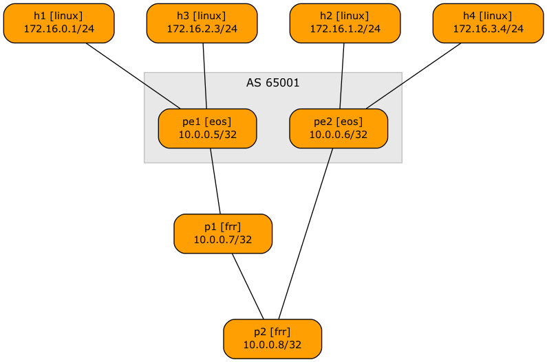
Lab topology
Here’s the lab topology we’ll use (also available on GitHub):
defaults.device: eosprovider: clabmpls.ldp: Falsegroups:_auto_create: Truehosts:members: [ h1, h2, h3, h4 ]device: linuxpe:members: [ pe1, pe2 ]module: [ isis, bgp, mpls, vrf, sr ]mpls.vpn: Truebgp.as: 65001p:members: [ p1, p2 ]module: [ isis, sr ]device: frrprovider: clabvrfs:t1:links: [ h1-pe1, h2-pe2 ]t2:links: [ h3-pe1, h4-pe2 ]links: [ pe1-p1, p1-p2, p2-pe2 ]
- We’ll use Arista EOS (line 1) running as cEOS containers (line 2)
- The lab will have four hosts implemented as Linux containers (lines 8-10)
- The PE-routers use VRFs and run IS-IS (IGP), BGP (in AS 65001), MPLS, and SR-MPLS (line 13)
- They use BGP AS 65001 (line 15) and use MPLS to implement MPLS/VPN service (line 14)
- netlab assumes you want to run LDP when using the MPLS module, so we have to disable LDP (line 4)
- The P routers are implemented with FRRouting containers to keep the memory requirements even lower (lines 19-20). They run only IS-IS and SR-MPLS (line 18)
- The lab has two VRFs, each with two links (lines 22-26)
- There are four core links, linking the PE-routers and P-routers in a chain.
After starting the lab, you can see multiple labels attached to remote VRF routes on PE routers, for example:
pe1#show ip route vrf t1 detail | begin Gateway
Gateway of last resort is not set

 M        0.0.0.0/8 PL
           directly connected, Null0
 M        127.0.0.0/8 PL
           directly connected, <Internal>
 C        172.16.0.0/24 PH
           directly connected, Ethernet2 pe1 -> h1 [stub]
 B I      172.16.1.0/24 [200/0] PL
           via 10.0.0.6/32, IS-IS SR tunnel index 1, label 116384
              via 10.1.0.1, Ethernet1, pe1 -> p1, label 16006
The (VPN) label 116384 comes from the VPNv4 route:
pe1#show bgp vpn-ipv4 172.16.1.0/24
BGP routing table information for VRF default
Router identifier 10.0.0.5, local AS number 65001
BGP routing table entry for IPv4 prefix 172.16.1.0/24, Route Distinguisher: 65000:1
 Paths: 1 available
  Local
    10.0.0.6 from 10.0.0.6 (10.0.0.6)
      Origin IGP, metric -, localpref 100, weight 0, tag 0, valid, internal, best
      Extended Community: Route-Target-AS:65000:1
      Remote MPLS label: 116384
The (transport) label 16006 is derived from SR-MPLS – the node SID for PE2 is six, and FRRouting uses 16000 as the start of its Segment Routing Global Block (SRGB). Please note that PE1 must use the label from P1 SRGB (16006), not the label advertised by PE2 (900006) to reach PE2 (more details).
pe1#show isis segment-routing prefix-segments

System ID: pe1                  Instance: 'Gandalf'
SR supported Data-plane: MPLS                   SR Router ID: 10.0.0.5

Node: 4      Proxy-Node: 0      Prefix: 0       Total Segments: 4

Flag Descriptions: R: Re-advertised, N: Node Segment, P: no-PHP
                   E: Explicit-NULL, V: Value, L: Local, A: Proxy-Node attached
Segment status codes: * - Self originated Prefix, L1 - level 1, L2 - level 2, ! - SR-unreachable,
                      # - Some IS-IS next-hops are SR-unreachable
   Prefix                      SID   Label Type       Flags                        System ID       Level Protection           Algorithm
   ------------------------- ----- ------- ---------- ---------------------------- --------------- ----- -------------------- -------------
*  10.0.0.5/32                   5  900005 Node       R:0 N:1 P:0 E:0 V:0 L:0      pe1             L2    unprotected          SPF
   10.0.0.6/32                   6  900006 Node       R:0 N:1 P:0 E:0 V:0 L:0      pe2             L2    unprotected          SPF
   10.0.0.7/32                   7   16007 Node       R:0 N:1 P:0 E:0 V:0 L:0      p1              L2    unprotected          SPF
   10.0.0.8/32                   8   16008 Node       R:0 N:1 P:0 E:0 V:0 L:0      p2              L2    unprotected          SPF
pe1#show isis segment-routing global-blocks

c - conflicting SR capability TLV, processed first advertisement
System ID: pe1                  Instance: Gandalf
SR supported Data-plane: MPLS                   SR Router ID: 10.0.0.5
SR Global Block( SRGB ) Size: 65536

Number of IS-IS segment routing capable nodes excluding self: 3

           SystemId         Base     Size
------- -------------- ------------ -----
   *            pe1       900000    65536
                pe2       900000    65536
                 p1        16000     8000
                 p2        16000     8000
Starting the Lab
The lab topology uses only containers so that you can run it in a Linux VM almost anywhere (including Windows Subsystem for Linux and on a Mac using Apple Silicon). All you have to do is:
- Install netlab in a Ubuntu VM
- Download and install the Arista cEOS container
- Open a terminal window and switch to an empty directory.
- Start the lab with
netlab up https://github.com/ipspace/netlab-examples/blob/master/MPLS/sr-vpnv4/topology.yml
If you want to run the lab in GitHub Codespaces, you have to
- Start a new codespace.
- Download Arista cEOS container into the codespace
- Change directory to
MPLS/sr-vpnv4. - Edit the topology file and change
device: frrtodevice: eosfor the P-routers (details in the Build an SR-MPLS Network with IS-IS lab exercise). - Start the lab with
netlab up.
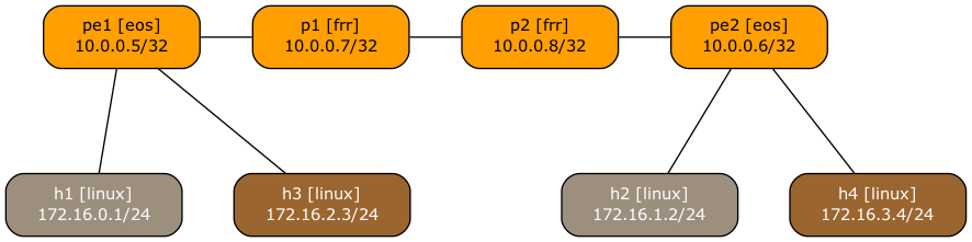
Pimp My Graph
The lab topology file in the netlab-examples GitHub repository has a few extra settings to make the topology graph look nicer:
groups:gr_core:members: [ p1, p2, pe1, pe2 ]graph.rank: 1gr_t1:members: [ h1, h2 ]graph.fill: "#9D8F7E"graph.format.fontcolor: "#FFF"graph.rank: 2gr_t2:members: [ h3, h4 ]graph.fill: "#9B652F"graph.format.fontcolor: "#FFF"graph.rank: 2defaults.outputs.graph.as_clusters: False
- The core devices have rank one (top row), hosts have rank two (bottom row)
- The hosts in the T1 VRF have a grayish background (line 7) with white text (line 8)
- The hosts in the T2 VRF have a brown background (line 12) with white text (line 13)
- The graph does not show BGP AS numbers (line 16) – using them would result in a weird-looking graph with P1 and P2 being outside of the AS. Want to try that? Install graphviz, modify the topology file, and execute netlab graph –topology topology.yml graph.png
FWIW, this is how the topology graph would look without the extra settings: